
Atomic-force microscope (AFM)
Atomic-force microscope (AFM) allows to determine the surface topography with in a scanning probe mode. There are several versions of AFM such as "Constant Height mode", "Constant Force mode", "Force Modulation microscopy", "Phase Imaging mode", "Kelvin Probe Force Microscopy", "Scanning Capacitance Microscopy" which allow to obtain high resolution surface images of various materials:
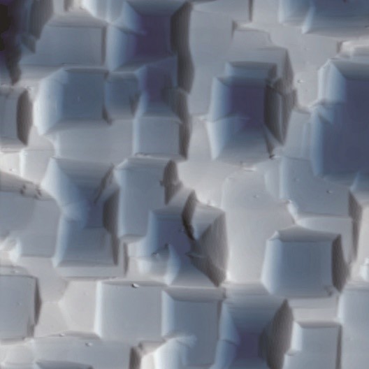 Unpolished Si
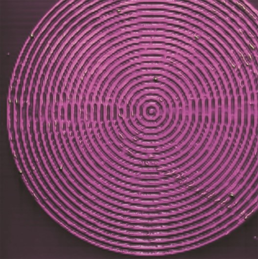 Microstructure on Si wafer
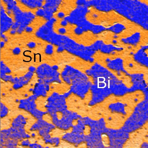 TIN-BI alloy
 Microstructure on Si wafer
AFM construction
Basic elements of the AFM include scanning element, feedback system, detector of deflection and motion of the cantilever (laser + photodiode), piezoscanner and vibration protection:
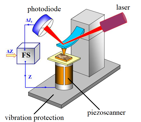
Scanning element = cantilever + sharp probe
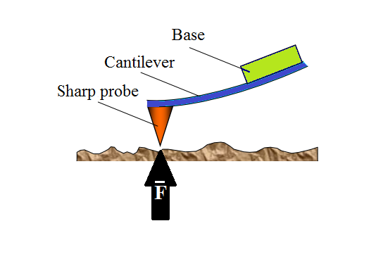
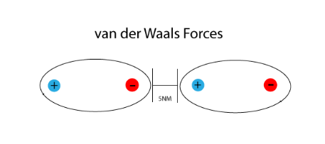
The interaction between the sharp probe and the sample is represented by the Van-der-Waals forces (the forces of intermolecular interaction with energy of 10-20 kJ / mol).
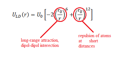
The interaction energy of two atoms can be approximated by the Lennard-Jones potential, where r0 - equilibrium distance between atoms and U0 - the energy value in the minimum.
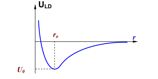
Except for an equilibrium position, there is a force (attractive or repulsive) acting on the cantilever which causes its bending of an elastic cantilever registered by the detector of deflection and motion consisted by a photodiode and a laser:
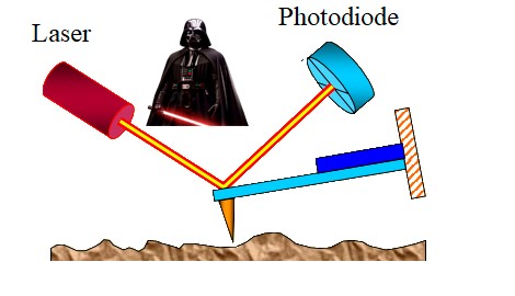
The laser radiation is focused on the cantilever, then reflected and falls on the photodiode. The semiconductor photodetector consists of 4 sections. With zero deformation of the console, the reflected beam enters directly into the center of the photosensitive region, while for any other deformation the position of the beam changes. Thus, any changes in the position of the console in space are recorded.
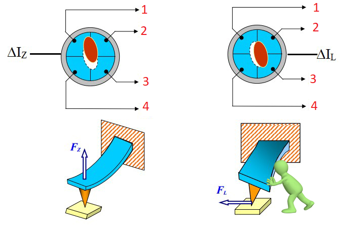
Since the photodetector consists of 4 sections, the displacement of the falling beam from the center of the photodetector causes different photocurrent values in each section:
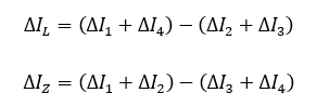
where ∆IL – the change in current that characterizes the bending of the console under the action of lateral forces, ∆IZ – the change in the current which characterizes the bending of the console along the normal to the surface. Before the measurement begins, the operator specifies a constant distance between the probe and the surface ∆Z0 consequently the parameter ∆IZ must be const. To fulfill this condition, a feedback system and piezoscanner are used.
Piezoscanner
It is necessary to control the probe-sample distance, and also to move the probe in the plane of the sample with high accuracy for the correct operation of the device. For this, a piezoscanner is used. Piezoscaner is made of piezoelectric, material that changes its shape under the influence of an external electric field (inverse piezoelectric effect)
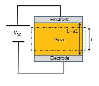
Tubular piezoelements (tube made of piezoceramic materials) have found wide application. They are able to significantly change their shape under small voltage. Under the influence of the potential difference between the inner and outer electrodes, the tube changes its dimension along the z axis or bends in the xy plane. Thus, longitudinal deformation under the action of a radial electric field has the following form:
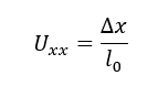
where 𝑙0 – original tube length and ∆𝑥 – absolute elongation of the piezo tube.
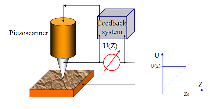
Feedback system
The feedback system helps maintain a constant parameter such as a distance between the probe and the sample, electrical interaction force, magnetic interaction force and friction force. The surface of the sample has irregularities, so the distance between the probe and the sample will change. The feedback system corrects this change by supplying the corresponding bias voltage to the piezo scanner.
AFM modes of operation
The AFM has 3 modes of operation include contact mode, tapping mode and noncontact mode.
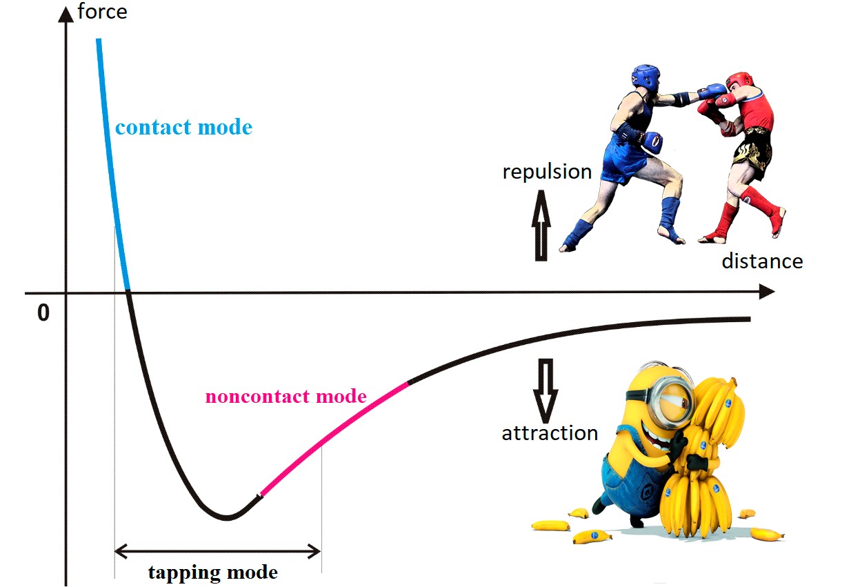
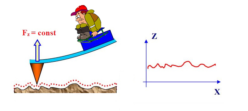
Contact mode:
In this mode, the tip of the probe is in contact with the surface. The forces of attraction and repulsion that act on the side of the sample are counterbalanced by the elasticity of the console. The relief of the surface is investigated with a constant force of interaction between the probe and the surface. The feedback system maintains a constant cantilever bending value. The interaction force between the probe and the sample is unchanged. Thus, the control voltage in the feedback system will be proportional to the surface relief.
Tapping mode:
In this mode, the cantilever oscillates with an amplitude of the order of 10-100 nm. The probe touches the surface in the lower half-cycle. The system records and maintains at a constant level the change in the amplitude and phase of cantilever oscillations during the sample scan. Interaction of the cantilever with the surface is equal to the sum of van der Waals interaction and the elastic force appearing at the moment of tangency, acting on the cantilever from the surface side.
Thus, to scan the surface, oscillations of the cantilever are excited at a frequency ω close to the resonant frequency of the cantilever with amplitude Аω, in turn, the operator specifies a constant amplitude of oscillations А0 < Аω. Since the change in the surface relief leads to a change in the amplitude, the feedback system compensates for this change by the shift of voltage. Therefore, the change in voltage defines the change in the relief.
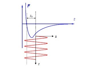
Noncontact mode:
The amplitude of forced oscillations of the cantilever is very small (1 nm) in this mode. When the cantilever approaches the surface, the force Fps begins to act on it. If the probe is at a distance z0, then
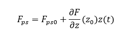
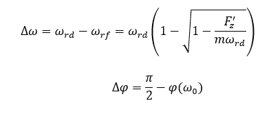
The presence of a gradient of the interaction force between the probe and the surface of the sample leads to an additional shift of the amplitude-frequency characteristic (∆ω) and the phase-frequency characteristic (∆φ) of the system:
Advantages of AFM
Advantages AFM include high-quality image of the surface relief at the nanoscale+ three-dimensional surface profile, unbreakable control and possibility to use with variety of optical microscopy and spectroscopy techniques such as fluorescent microscopy of infrared spectroscopy. To obtain a high-quality image the following aberrations must be eliminated from the obtained signal: a constant slope that may result from an inaccurate installation of the sample relative to the probe, presence of interference during operation of the equipment, instability of probe-sample contact, presence of interference due to external vibrations.
Acknowledgement

Content of the web page has been developed by Pavel Brudnyi, undergraduate student of National Research Tomsk State University.
High resolution AFM images have been taken from NT-MDT Scan-Gallery.
Figures have been taken from the book of Victor L. Mironov, Fundamentals of Scanning Probe Microscopy.